www.electronics-usa.com
25
'21
Written on Modified on
Mouser News
Analog Design Tools and Resources
In this, the third blog in our series covering the importance of analog engineering skills, we look at the lab equipment electronics engineers need to perform their role.
We’ll review the functions and operation of hardware tools – the power supply, signal generator, an oscilloscope, and show how their once discrete functionalities have now been combined into a single, convenient USB powered tool, before also discussing the features of a software tool that has greatly simplified the process of designing analog filter circuits.
Laboratory Equipment When Working with Analog Circuits
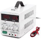
The purpose of an electronic circuit is to control and direct electric current to deliver a variety of functions. For testing the performance of any analog circuit design a power supply is a critical tool. A power supply (Figure 1) operates by rectifying an ac voltage to generate pulsed dc, which is filtered producing a smooth voltage. This voltage is then regulated, creating a constant output level that is unaffected by changes in ac input voltage or circuit loading.
In a lab environment, electronics engineers use a benchtop DC power supply (which may have additional features, depending on specification) to re-create the power source that a circuit will use in a field application. Using rotary controls allows the regulated DC voltage and current outputs to be set more precisely. Some standalone power supplies are programmable, meaning they can be connected directly to a laptop computer which can then control them.
A signal generator is used to create repeating or non-repeating waveforms, allowing engineers to select the size, shape, and frequency of the test signal required. Sine, triangular and square wave options are typically provided, with pushbuttons to select frequency control and rotary controls to tune amplitude. Higher specification models are programmable and may also include an LCD screen.
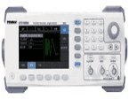
Figure 2 Signal generator
Visualising Analog Signals
Traditionally, engineers have used an oscilloscope; a large benchtop instrument with an LED screen to view analog signals. However, new types of ultra-portable devices, like the Digilent Analog Discovery 2 combine the functionality of an oscilloscope, signal generator, DC power supply, and voltmeter, packaged within a compact footprint. These “USB connected” devices are easily configured using a laptop computer, which can also be used for signal display. Form and functionality make these kit solutions ideal for engineers to perform tests and signal analysis virtually and in any environment.
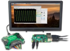
Figure 3 Digilent Analog Discovery 2
Designing Filter Circuits
Once an engineer has established their filter circuit specifications, they then determine the circuit configuration needed to achieve it. Traditionally, this required them to mathematically calculate the filter’s transfer function (equation) then select the components (capacitors, resistors, and op-amps) to build it. This can be a time consuming and sometimes difficult task, but has been greatly simplified by the availability of software tools like Analog Filter Wizard from Analog Devices, which allows the electronics engineer to design a filter circuit in five simple steps:
Step 1: Select Filter Type
Choose the type of filter required (low-pass, high-pass, or band pass)
Step 2: Specifications
The ‘Specifications’ tab allows them to input the gain, passband, stopband, and filter roll-off and to investigate the trade-off between speed versus the number of stages, using a slider. The tool also displays a graph of the filter’s frequency response, which immediately updates when input specifications are changed.
Step 3: Components
The ‘Components’ tab displays the circuit configuration and physical component values (R, C, and Op-Amp) required to meet the filter specification.
Step 4: Tolerances
Here engineers can specify the tolerances of the circuit components they choose. While lower tolerance components can cost less, and be more readily available, they may increase variability between individual filter instances. This trade-off between cost, performance, and availability should be fully considered by applying “design for manufacture” - a strategy that mitigates the potential risk of incorrect component specification early in the design process.
Step 5: Next Steps
This allows the engineer to download SPICE files for the filter circuit – a useful feature that allows them to simulate the ‘real-world’ performance of the filter circuit.
Circuit Simulation
SPICE software tools allow the simulation of circuit behaviour in practical applications. By modifying variables such as the power supply voltage and temperature, engineers can determine the tolerances which are acceptable to each circuit well before committing to building a physical prototype - both costly and time-consuming. Electronics engineers can also specify a variety of input signals, voltage/ temperature variations, and simulation types that allows them to analyse circuit behaviour in terms of both time and frequency.
Conclusion
The latest generation of hardware and software tools greatly simplify tasks commonly performed by electronics engineers when designing analog circuits. The functionality of the power supply, signal generator, and oscilloscope have been combined into standalone, ultra-portable instruments like Digilent’s Analog Discovery 2. While the process of designing an analog filter circuit has been made easier by the availability of software tools like Analog Filter Wizard by Analog Devices. In our next article, we will demonstrate how analog circuit simulation has been made much easier by SPICE software simulation files.
Stay tuned for the next blog in the series: Getting to grips with analog design.
www.mouser.com